Charging LiFePO4, what’s the impact of lower voltages?
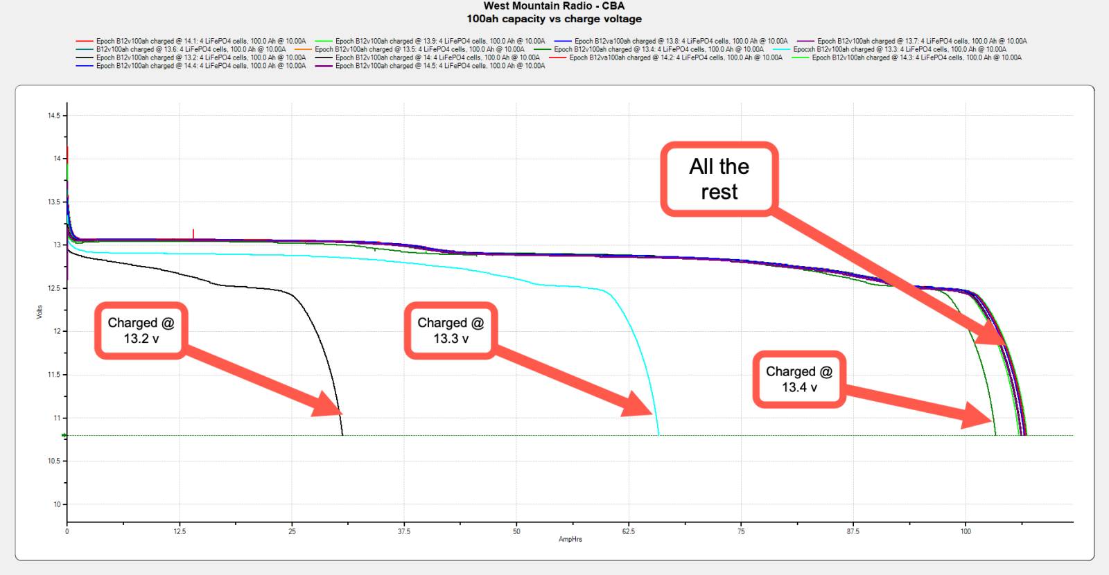
What voltage should I charge my LiFePO4 batteries? That seems like a simple question likely to have a single, direct answer. But, the actual answers are often unclear. Many LiFePO4 battery manufacturers recommend 14.6 volt absorption. But, that singular recommendation doesn’t account for numerous factors like managing a larger system, battery longevity, and more. Increasingly, we are seeing good reasons to lower charge voltages to 14 volts or below. But, what impact does that lower charge voltage have on capacity and charge time? Let’s take a look.
Recently in my testing I have seen several 12-volt Epoch Batteries equipped with a feature that disconnects charging when the BMS sees charging over 14 volts and under 3.5 amps. This feature attempts avoid damage to the battery from extended high voltage charging. But, it also comes with some unintended consequences as charge sources aren’t designed for disconnection while charging.
Preventing charge disconnects isn’t the only reason to use a low absorption voltage with LiFePO4 batteries. Rod Collins of MarineHowTo has long advocated for lower charge voltages. In fact, he has a 15 year old, 400 amp-hour battery he built back in 2010 that he exclusively charges at 13.8 volt absorption. That 15 year old battery has done more than 2500 cycles and still tests over 103 percent of rated capacity.
LiFePO4 battery manufacturers regularly call for an absorption voltage between 14.2 and 14.6 volts. So, what are the ramifactions of charging at a lower voltage? First, keep in mind that in lead acid batteries we use a relatively high absorption voltage in order to put some heat into the batteries and sluff off any sulfation that may have formed on the battery. With LFP batteries, that isn’t a concern or necessary.
So, the two main factors likely to be impacted by lower charge voltages would be capacity and charge time. Specifically, we want to know if the battery delivers less power if charged at, for example, 13.8 volts than it will if charged at 14.4 volts.
Testing capacity and charge times
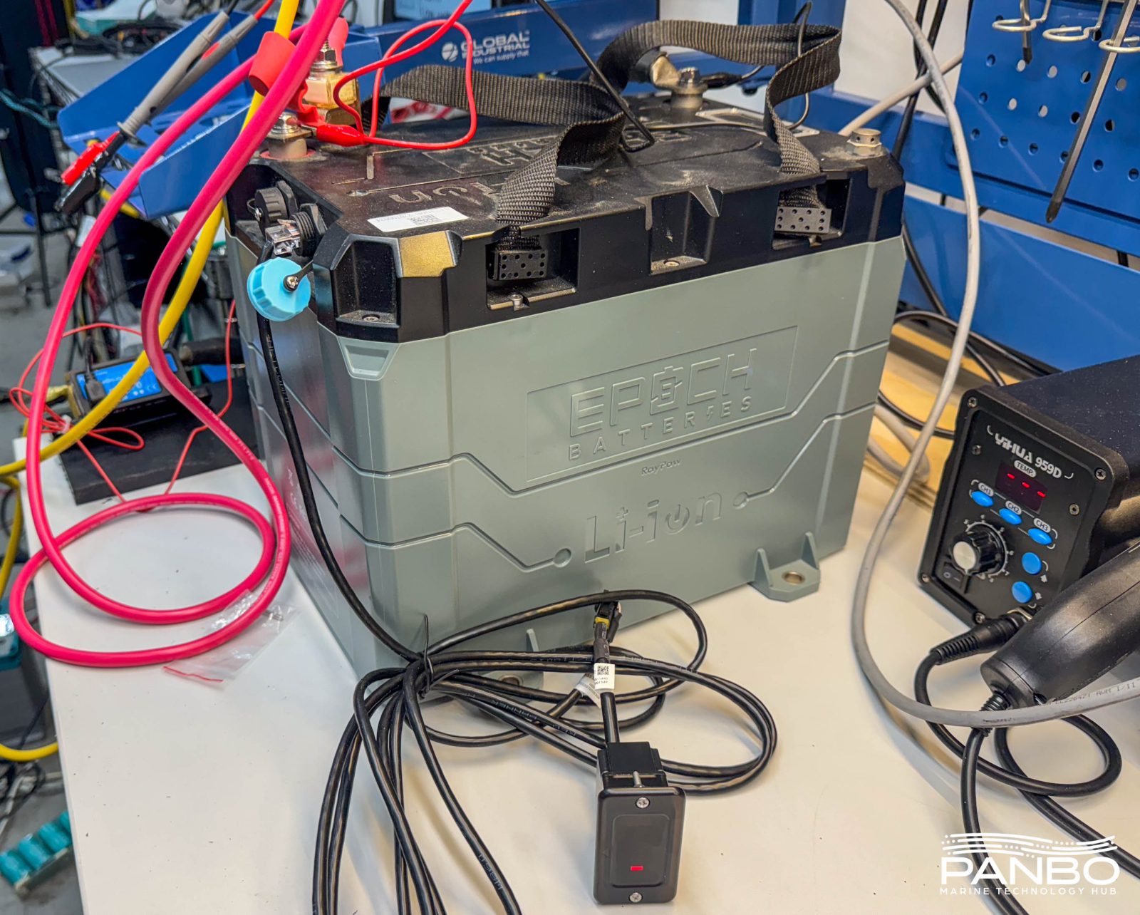
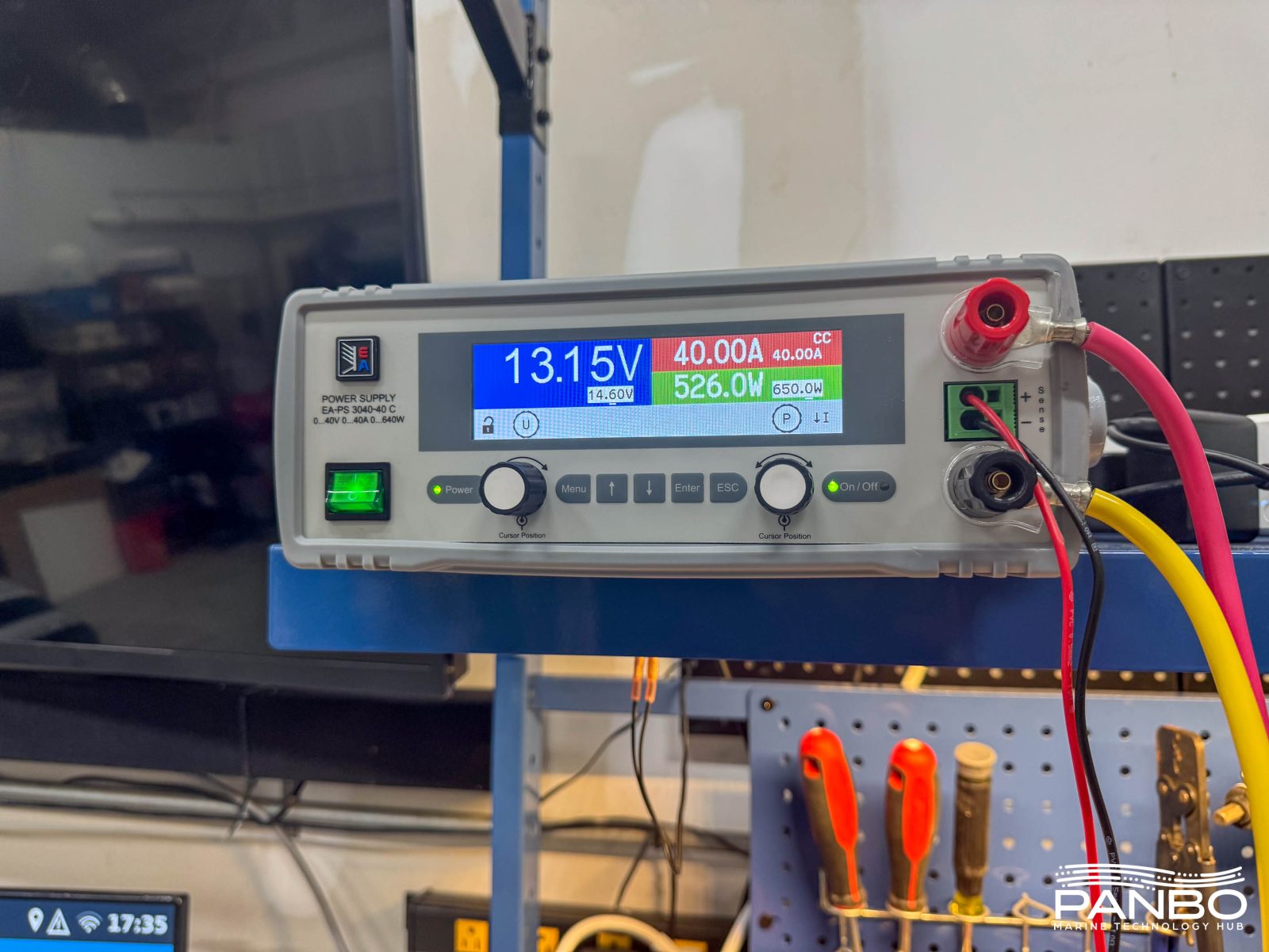
To understand the impact of lower voltage charging, I’ve done a series of tests with a 100 amp hour Epoch 12-volt battery. I reviewed these batteries early last year — and missed the full charge disconnect feature — and found they regularly delivered well over their rated capacity. Using a 40 amp, electronically controlled power supply, I fully charged the battery from 13.2 to 14.2 volts. My power supply uses sense leads to ensure the battery measures the correct voltage at its terminals.
I then tested the capacity using a 10 amp discharge rate. Effectively, this is a 10 hour capacity test for this battery. That’s more aggressive than a BCI 20-hour capacity test but gives a basis for comparison. I selected a 10 hour test just to try and minimize the time required to complete the tests. I don’t expect the capacity numbers would be very different with 20 hour tests. LFP batteries have a much lower Peukert’s exponent than lead-acid; meaning the discharge rate has a smaller impact on capacity.
| Charged voltage | Capacity @ 10 hour rundown | Charge time (hh:mm) |
| 14.6 | 105.96 ah | 2:45 |
| 14.5 | 106.14 ah | 2:46 |
| 14.4 | 106.51 ah | 2:48 |
| 14.3 | 105.90 ah | 2:50 |
| 14.2 | 106.56 ah | 2:51 |
| 14.1 | 106.49 ah | 2:51 |
| 14 | 106.67 ah | 2:53 |
| 13.9 | 106.89 ah | 3:37 |
| 13.8 | 106.7 ah | 3:43 |
| 13.7 | 106.69 ah | 3:59 |
| 13.6 | 106.6 ah | 4:39 |
| 13.5 | 106.15 ah | 6:15 |
| 13.4 | 103.32 ah | 17:10 |
| 13.3 | 65.83 ah | 10:49* |
| 13.2 | 30.59 ah | 8:28** |
As we can see in the data, capacity really doesn’t vary until we drop below 13.5 volts absorption. But, while capacity is quite stable, lowering absorption voltage steadily increases the time it takes to reach full charge. At 13.4 volts, it takes a full seventeen hours and ten minutes to achieve full charge. Absorption voltage below 13.4 doesn’t fully charge the battery. Using a 40 amp charger to replace 106 or so amp hours, the theoretical minimum time would be two hours and thirty nine minutes. By 14.1 volts, we are within 12 minutes of that figure and not likely to improve much due to charge taper near 100 percent SOC.
Time to absorption
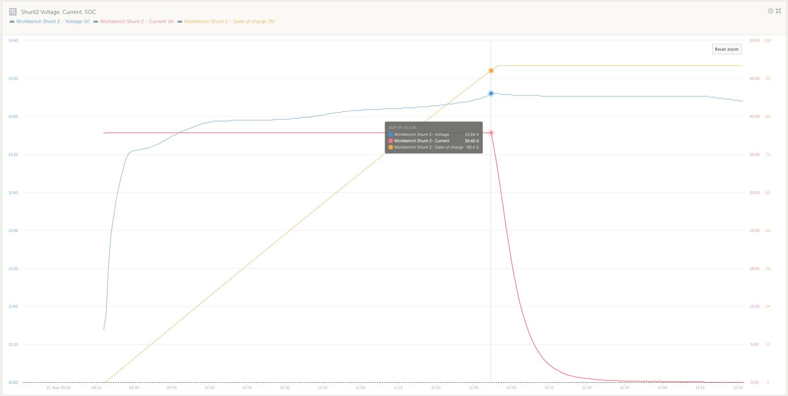
My first thought when I looked at the results was, well capacity doesn’t take much of a hit, but charge time sure does. However, it occurred to me that the additional time is probably mostly at the very end of charging as the battery has already reached a high SOC. Indeed, the chart above shows the details for charging to 13.9 volts. It took two hours and forty one minutes for the battery to reach the transition point from bulk to absorption. At that time, SOC measured at 98.4 percent. The remaining 1.6 percent took an hour and ten minutes. Effectively, that last 1.4 percent is likely inconsequential.
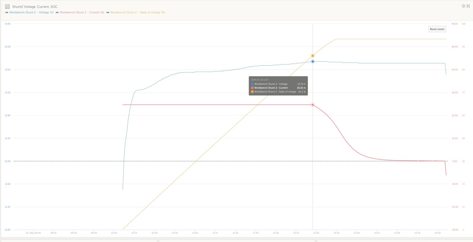
I was equally surprised to see how quickly the transition point moves when you decrease charge voltage. As is depicted in the graph above showing charging at 13.9 volts, by decreasing charge voltage by just one tenth of a volt, the transition to absorption or constant voltage charging occurs at 91.2 percent, a full 7.2 percent sooner. I submit that potentially missing out on nearly nine percent of a battery’s capacity is of greater consequence.
What have we learned?
If you took the time to read this article, it is probably because you’re trying to figure out charging settings for your LiFePO4 batteries. So, what conclusions can we draw from the data? Overall, I think we can conclude that a charge setting of 13.9 volts won’t meaningfully impact the capacity of your battery bank. In fact, I suspect you wouldn’t ever notice any difference in capacity. It is possible you will there will be a barely perceptible difference in charge times..







I had some idea that this would be the case, but this testing actually confirms it to an even higher degree than I fugured. I have settled on 13.9 bulk/ absorb and 13.5 float. The next question would seem to be…how does this slightly lower charge voltage affect the cell balancing on a typical drop in with passive balancing over the long term. I have noticed Litime has a similar full chg protection as well. Thanks for all the great testing Ben. Much appreciated.
Ben,
As you know I was working on this exact article but the testing takes time. I had a few more tests to run, this just saved me the time.
I will just point out that it is hard to find a charger that has less than a 1 hour absorption so 13.8V -13.9V is not going to cost you much capacity at all. I knew all this back in 2009 from testing and is how I arrived at 13.8V for absorbing my 12V pack..
Also just realized these graphs say that floating at 13.5 still keeps you very close to full capacity, while floating just one tenth lower at 13.4 has some actual capacity loss. So it appears at least for this battery, to keep SOC meters more in sync and accurate after the full charge cycle has ended, floating at 13.5 would be significantly better than floating at 13.4. Especially if floating for extended periods. I always figured 13.4 or 13.5 for float…whatever. But this data says otherwise.
In addition in conjunction with your last article on the Epoch 460 comms and DVCC, you probably could use the Victron Comms and DVCC (which we know results in a single stage charge profile) and keep the bulk/absorb/float at something like 13.6 or 13.7. I doubt holding these cell at 13.6 or 13.7 would result in adverse effects over the long term and just comes at a cost of charge time. Many manufactures state to float at 13.8. Not that I would prefer that. It would seem you would want to float at the lowest voltage that does not incur meaningful capacity loss. Which according this data is 13.5.
Also just realized these graphs say that floating at 13.5 still keeps you very close to full capacity, while floating just one tenth lower at 13.4 has some actual capacity loss. So it appears at least for this battery, to keep SOC meters more in sync and accurate after the full charge cycle has ended, floating at 13.5 would be significantly better than floating at 13.4. Especially if floating for extended periods. I always figured 13.4 or 13.5 for float…whatever. But this data says otherwise.
In addition and in conjunction with your last article on the Epoch 460 comms and DVCC, you probably could use the Victron Comms and DVCC (which we know results in a single stage charge profile) and keep the bulk/absorb/float at something like 13.6 or 13.7. I doubt holding these cells at 13.6 or 13.7 would result in adverse effects over the long term and just comes at a cost of charge time. Many manufactures state to float at 13.8. Not that I would prefer that. It would seem you would want to float at the lowest voltage that does not incur meaningful capacity loss. Which according this data is 13.5. But holding the cells at 13.7 probably has no adverse effects.
Rod or Ben or anyone…given this data what is your feeling on charging and floating at 13.7 for the Epoch 460 with DVCC back on. It seems odd. But it may in fact be just fine given this narrow window of what voltage constitutes “full” capacity vs what voltage are considered safe in the long term. I do know that many off grid guys do just that at 13.8.
Maybe these Chinese engineers do know a thing or two..lol.
Excellent information Ben!
Thank you for posting this data. Andy from Off Grid Garage has come to very similar conclusions based on his testing.
For the Epoch LFP’s there does not appear to be any advantage to bulk absorption voltages higher than 13.8-13.9 VDC but deciding on the ‘float’ voltage is less clear-cut…
The common wisdom has been that LFP does not do well with the cells held at a continuous 100% SOC. Is this still true?
Assuming the house bank will have to service ongoing loads while a vessel is on shore-power, what is the optimal float voltage to keep the house bank in a good, ready to cast off, SOC?
In other words, What is the maximum safe steady state SOC we should aim for?
I’ve seen very little evidence to support the notion that damage is done or life is shortened by holding LiFePO4 batteries at 100% SOC as long as the voltage isn’t elevated. So, I don’t think any damage is done holding batteries at or near 100% SOC with a 13.4 or 13.5 volt float. Allen asked a question about using a single stage charge at 13.7 volts and personally, I’m not comfortable with that yet.
-Ben S.
Thank you Ben.
I have been playing with a few float settings but it’s been tricky to get a float value that settles reliably into my target of ~ 90% SOC range. If being at or close to 100% SOC at 13.4 V float is OK & not harmful to the cells , that would be excellent and easily achievable.
Could you post the 14.0v to 14.4v curves that you show in the blog for 13.8v and 13.9v? The data might be easier to parse in a table but the time to get to the absorption phase and time in absorption until full (100% SOC) seems like a crucial discriminator for choosing the charge voltage.
I know many like the lower charge voltage for longevity but that seems an optimization that may be much less important to others, but having data to support these “best charge voltage” decisions seems to be the best approach. Thank you.
Thank you for this very valuable info. I know that it took a lot of time and effort to collect and analyze. There are a lot of opinions out there, few of which are grounded in as detailed analysis that you’ve provided. I spent the majority of my career working for the largest test and measurement equipment company and we had a saying which I’ll paraphrase as, “Until you make a measurement, you don’t know what the heck you’re talking about.”
Well done! Looking forward to more of the same.
Thanks for all the work you have done with the 460s which helped a bunch in my new install! Also thanks go out Allen and Jim Duke.
Ben-
Excellent and detailed investigation. As I looked at your data I had to greatly admire the details you had to overcome to collect this data over weeks of effort and then boil it all down. But I have a question. What part does the BMS have to play in this charging scheme? Doesn’t the wide variation in BMS types have a big impact on these measurements? Or are we assuming you are charging “direct” to the cells with no BMS involved? Assuming the BMS plays a role it seems that the small changes in tenths of a volt in Absorb voltage could also be related in part to the BMS control device technology – GaN FETs Vs CMOS etc with different CE (Collector to Emitter) voltage drops could have an impact on how much charge is reaching the cells. Seems like there are huge unknowns running around in the BMS in addition to the specific nature of the LiFePo cells and their varying manufacturing methods.
I have no clue how to resolve these questions. I will say that for now, my poor old brain just wants my WS500 to take care of my $5K investment in my bank of 4 – 8D old fashioned AGMs and all of this research points out that optimizing the capacity and longevity of LiFePo batteries is worthy of years of experiment and discussion.
I can see the benefit of LiFePo on sailboats in particular where there is usually far less room for huge collections of AGMs. The great capacity Vs Volume and weight provides great benefit for modest sailboats. I helped a great friend rig a nice dual AGM (Start – Motoring Battery) and LiFePo (Solar Charged) for sail and at anchor. This dual scheme only required investment in a VE MPPT solar charger and the rest of the gear on his 30HP Diesel and Charger inverter remained the same. Battery switching isolated the loads so that only one type of battery was in use at one time. He is loving it and is happily cruising the Broughton Archipelago in BC Canada now. So long as his VE MPPT keeps his LiFePo going he is happy and will never be aware of all of this research. But if he does see the battery capacity tail off I can refer him to all of this knowledge so he can keep his investment going.
Thanks tons for the work!
The only downside with the “short-charging” is that the BMS has a harder time balancing the cells. The cell differences in capacity show up when reaching full voltage.
So a higher-voltage charge every now & then is still a good idea. Just don’t leave them at high voltage for long periods; just get the voltage up >14.0-14.2 for 30min which should be plenty for balancing if done once a month or so. Then discharge them a bit, and cycle away between 13.0 and 13.8 or whatever, to your heart’s content…
I am using a Magnum inverter to charge my Epoch 460ah battery and have found that the charge cycle won’t stay in Bulk, but rather quickly switches to Absorb charging with a set charge voltage of 13.8. The current draw early in the Absorb cycle is approximately at my set value of 80 amps (the charge cycle looks very much like a bulk charge even though the Magnum is in Absorb). Later in the charge cycle, as it approaches the full battery capacity, it tapers to zero amps. The Absorb control is only done with a time setting so the display will show Absorb charging at 0 amps. The battery and shunt confirm there is no current being supplied for charging even though the display still shows the absorb cycle is still ongoing. It takes approximately 3 hours to recharge the battery with these settings. I have the final charge on the Magnum set to Silent, so that the charger shuts off completely until I hit my Rebulk setting of 13 volts. If I don’t use the Silent final charge setting but rather use the Float, the rebulk is 12 volts by default and that can’t be changed. Once the charge cycle enters Silent mode, the Magnum will then draw 2.1 amps from the battery to monitor for the next charge cycle that occurs in about 5-6 days. Even though I am using the Custom setup on the Magnum, the settings make it behave like it is CC/CV charging.
Hi Bob,
I only use my Magnum for bulk charging on the generator.
It’s Much simpler to use a reasonably cheap and much more programmable Victron IP22 while on shore power to maintain the Epoch’s while docked at home.
Great article and great analytics Ben. Thank you. Using a bench supply makes sense for this testing. In the real messy boat world of multiple charge sources there are a lot of trade-offs. What I am finding is when charging from alternators (either my 100amp engine alternator or from my 6HP Kubota 12V genset/scuba compressor (homemade setup) if I set the charge voltage to 13.9 vs 14.2, there is a very significant difference in the amps flowing to the batteries. In this case, the charge time difference is grossly exaggerated with lower charge voltages. I am using a alternator regulator that monitors both battery and alternator amps and of course alternator temperature (my improved version of Bill Thomason’s open-source VSR Alternator Regulator). At 13.9 volts, the charging is limited by the voltage. At 14.2, it tends to be more limited by the alternator temperature feedback, while providing a lot more current (almost twice as much). So from a diesel fuel and engine wear perspective, the higher voltage may win. Your thoughts?
Pete,
I can’t say I’ve tested this, but I strongly suspect the issue is the location of voltage measurement. If the alternator is being regulated to produce 13.9 volts at the alternator, you will likely find significantly lower voltage reaching the batteries. I suspect that lower voltage at the batteries is what accounts for the big delta in current acceptance and hence charge times. The bench supply I use has remote voltage sensing. If I use another one that doesn’t, I often have to boost voltage to keep charge acceptance in range.
-Ben S.
Hi Ben, I think I did a poor job of communicating my observations… let me try again. First though, to your comment, of course I am using dedicated, twisted pair, remote voltage sensing for my ‘VSR Mini-Mega Alternator Regulator” (Which is based on the open-source design that became the commercial product known as the WakeSpeed WS-500 which Panbo reviewed a long time ago). (I wouldn’t be much of an EE if I didn’t at least to that…) So back to my observation…
It really boils down to this… assuming the battery can accept both the voltage and current, as a LiFePO4 battery can as compared to a lead-acid battery (Gel, AGM, etc), then as the alternator field current is increased, BOTH the voltage AND current increase from the alternator. So, when we decide to charge at a higher voltage, the alternator will also generate more current, unlike in the fixed-current bench test that you used in your excellent article. So, in the real world, using an alternator, increasing the charge voltage also increases the charge current so the charge time dramatically decreases in more of a geometric curve than a linear one, unlike in the bench test illustration. (Do you disagree?)
Now further, as I use this “VSR” regulator with BOTH battery current and alternator current shunts (whereas most regulators have neither…), I (and the regulator) can see both currents (current to the battery and current from the alternator) and manage the charging accordingly. I therefore also set a battery current limit for the battery bank, an alternator current limit for my 12V genset, and a separate alternator current limit for my engine (that is, with the engine and genset each having their own dedicated VSR regulators). So, back to the real world… I can for example, set the battery charge current limit at 250 amps, the genset alternator current limit at 125 amps, and the engine alternator current limit at 100 amps, leaving another 25 amps of “headroom” for solar charging (250-125-100 = 25). It is, with these settings, then be possible to run both the engine and the genset simultaneously and on a sunny day charge the batteries at a rate of 250 amps, which is still way below the charge current limit specification of the battery bank. And what I find when I test this is exactly that… the alternator controller manages the alternator current at these limits (which, incidentally is also within the capabilities of my alternators without going beyond the thermal roll-off settings I have set on the alternator controllers) and see exactly 125 and 100 amps from the respective alternators and a number a bit higher than that flowing into the batteries when the sun is overhead. Why all alternator controllers don’t work this way is beyond me.
Pete,
Glad to hear you are using remote voltage sensing. With that additional detail layered in, I think you’ve provided a great real world data point about the mix of alternator charging and solar charging. There’s no question that the means of power generation or conversion matters when it comes to understanding the behavior. You’ve provided an important distinction between the toroidal transformer in my bench power supply and rotary power created by an alternator.
In cases, like what your example with alternator charging, where current and voltage move together, I would indeed expect non-linear changes in charge times as they decrease. Frankly, I haven’t been able to do enough controlled testing with alternators to say any more with confidence. I’ve been working to figure out a way to include controlled alternator testing for quite some time. I think it’s high time I step up those efforts!
-Ben S.
Just like Ben’s bench power supply with v-sense, a properly wired voltage regulator will not limit current until absorption voltage is reached.
@Anonymous… Not exactly correct. With MOST regulators which only monitor voltage that’s true. Notice please that the VSR regulator uses not only voltage and temperature sensing but also current shunts on both the battery and the alternator As such, the alternator output is primarily managed to the regulator’s setting value for maximum alternator current, which is secondarily reduced if the setting for alternator temperature is exceeded. Then the battery maximum current is considered (taking into account multiple simultaneous charge sources. And finally the voltage limits the charging cycle stage, taking current down to a float level when the target voltage is achieved. The alternator field current is adjusted using a OID algorithm which Al Thomason developed in open source.
This is the ideal charging regulation which regulators with two shunts cannot possibly achieve.
Edits… PID. Not OID.
“without two shunts*cannot* achieve
Edits… To my comment… PID. Not OID.
“without two shunts*cannot* achieve
I’m using Battleborn LFP batteries and per their technical support the BMS does a top end cell balancing that doesn’t kick in until 14v. They recommend a 14.2-14.4v absorption voltage to ensure cell get balanced. While off the grid I try to get to 100% SOC at least every 2 weeks to ensure cell balancing.
That’s interesting William and very useful for folks with Battleborn batteries to know.
When using the “generic” BMS systems, like the JBD or Overkill Solar brands, they can be set to balance only while charging or while charging/not charging. So folks using “home built” battery banks have more control of things (many, many potential settings besides just this one) and the cells balance pretty much any time they need to.